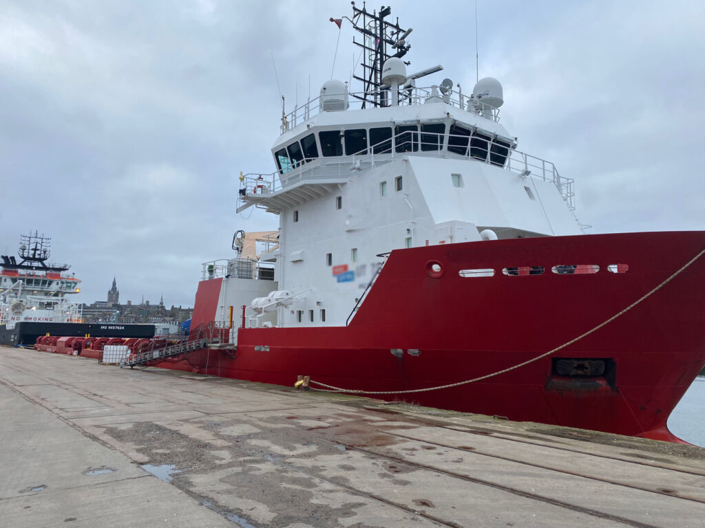
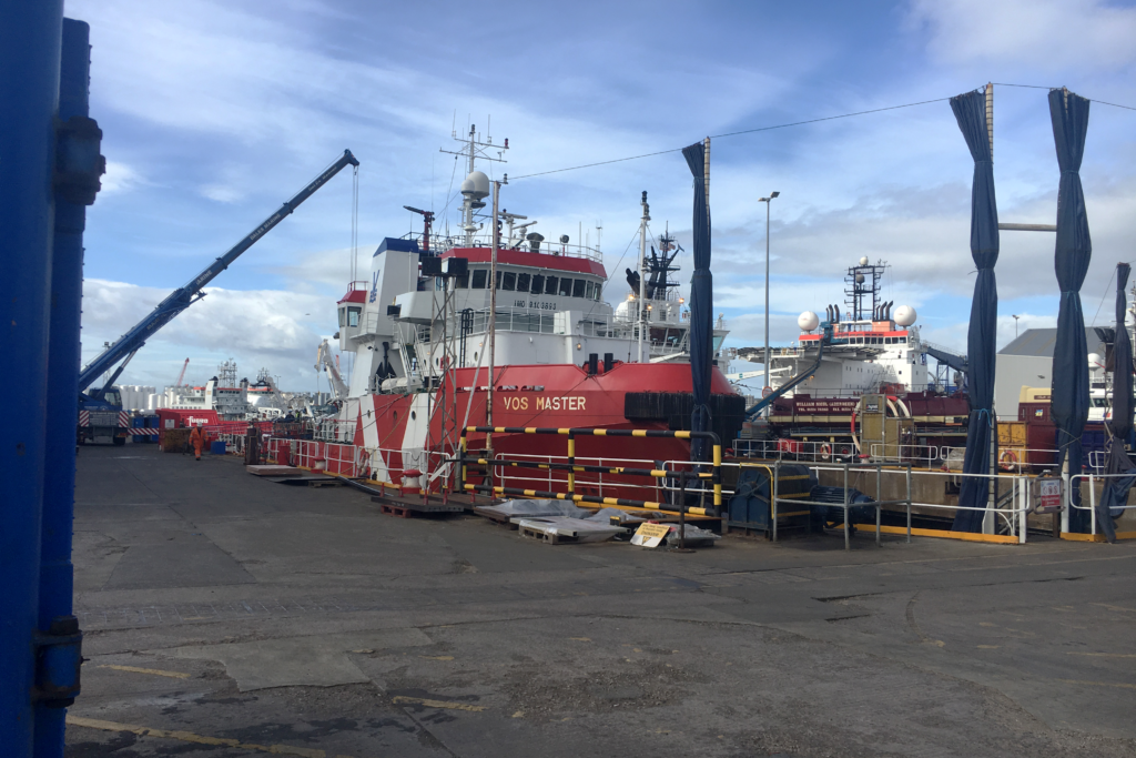
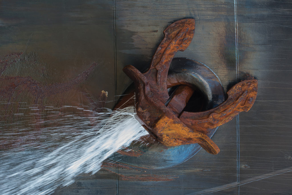
Several different components can make up a complete propulsion line including engines, generators, gearboxes, line shaft, bracket and stern tube support bearings, stabilisers, rudders and thrusters. System performance, life and noise rely heavily on accurate alignment of these component parts. Assuring correct alignment of the equipment is a key part of installation, maintenance and fault finding in managing the propulsion system through its operational lifetime. These are all areas in which AtZ can provide supportive product and services.
Shaft Tube Alignment

Shaft alignment is the process of aligning two or more shafts of interconnected machinery to within an acceptable tolerance margin.

Any difference in alignment between the connected systems will increase noise, vibration, heat generation and ultimately contribute to a shorter equipment lifetime and possibly a catastrophic failure.

Types of Misalignment

Parallel misalignment – where the shaft axes remain parallel, but their centres are offset in either the horizontal or vertical plane.

Angular misalignment – where the shaft axes are at an angle to each other but remain in the same horizontal or vertical plane.

Misalignment of the systems can be a combination of both types of parallel and angular misalignment.

System Alignment

In general alignment of systems during a survey is conducted with systems shut down, with any rotation of interconnected components achieved manually with turning gear.

System alignment can be checked while in operation using accelerometers placed along a shaftline, but this is generally reserved for observation over time and condition monitoring to identify any changes in system performance.

In connection with shaft alignment within a system survey, additional measurements may be taken to assess the impact on associated systems such as seals. This could include:

STRAIGHTNESS MEASUREMENT

By definition – a straight line is the shortest distance between two points in space, and should any items be bent, kinked or damaged along their length strength and system performance could be compromised.

Straightness of rails, supporting structures, vessel hulls and similar are assessed using a reference straight line. The distance along the checked component from the reference line is measured.

LINEBORE MEASUREMENT

Within a mechanical structure, a bore is the inner diameter of a cylinder – a hole. It is used to support other machinery such as bearings, seals and bushes. They can be found throughout engines, generators, gearboxes, stern tubes, stabiliser and rudder installations. Measurement is achieved by placing a reference line in the known central position and checking distance from it along the length of the bore. From this reference line, bores can be measured in vertical, horizontal, forward and aft directions.

FLATNESS MEASUREMENT

Flatness is a measure of the quality of a surface with respect to changes in its height over the entire surface. Accurate alignment of any system relies heavily on a solid foundation reference as any undulations across a surface will be transferred into the system resting upon it. A reference plane is established from which changes in the surface being measured are assessed and compared to the required system tolerances. Performance of machines, slewing and guide bearings depend heavily on flatness for performance and is a parameter that would be assessed during a survey on rudder or podded propulsion systems for example.

PERPENDICULARITY MEASUREMENTS

Most rotating equipment is designed to operate when at a right angle to its counterpart. Deviation from the 90degree interface will contribute to friction, wear and seal leakage. This is particularly important with rudder machinery, actuators, seal housings and components associated with thye stern tube. Checks of perpendicularity would be included within a full shaft alignment survey as required.

PARALLELISM MEASUREMENT

This is a measurement of how close to the same distance two parallel sit from each other.

In propulsion components such as engines and gearboxes, gear wheel drives, rotating seal faces and couplings rely on good parallelism to minimise friction, wear and deliver optimum system life.


FAQ’s

My system has a flexible coupling with a large misalignment tolerance – why do I still have to align my equipment accurately?

Flexible couplings are intended to dampen vibrations, reducing noise and shock loading. Flexible couplings can absorb some misalignment, but the greater this is, the larger the forces on the component. This will result in unnecessary noise and vibration through the system as well as increased heat generation and reduced life of system components. An accurate alignment is always of benefit.

Are bearings of propulsion shafts always aligned along a single straight line?

In short – not always.
When considering alignment of a complete shaftline, the weight of the shaft, loads upon it, the components mounted on it and the movement of the hull or other structure supporting it under load need to be considered.
In most cases a computer model of the complete system is used to predict the movement of the system under various load conditions. The outputs from this simulation include any slope or offset required within the bearings in order to ensure optimum support of the shaft in operation. It will also give expected bearing loads at various points along the shaft which can be used to check operation by raising the shaft and measuring the force required (jack up method).

Is laser alignment a more accurate method than dial indicator alignment?

Not necessarily – they tend to be used in different circumstances.
Laser alignment equipment is generally used where two coupled shafts can be rotated. In the case of an uncoupled propeller shaft, use of a dial indicator is both more convenient and accurate owing to the difficulty of rotating an uncoupled shaft.

Your Industry Is Our Industry

Talk to our team of technical experts

Our team of technical experts offer industry-leading consultation services, equipment sales and support and with a wealth of project management and technical experience, we plan and deliver. We work with you to ensure a smooth project from design specification to onsite installation. Our impartial guidance and multi-supplier approach mean we are focused on finding you the best solution meaning you can be confident in both our services and products.

Talk to us today Download Brochure
Top